Dancing Light using 555 Timer

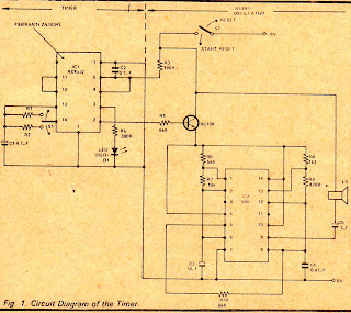
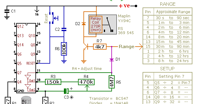
6 Hour Timer Circuit Diagram

Clock circuit digital timer 24 hour diagram electronic based microcontroller without projects simple counter driver time crcuit electronics Circuit circuits timer hour delay gr next

Timer circuit 24 hour timer :: circuit diagrams Timer of 12 seconds using hardware circuit

Timers and Counters Circuits, page1

Circuit timer hour clock digital programmable

Using circuit schematic seconds timer hardware circuitlab created

Timers and counters circuits, page1Simple 1 hour timer circuit with buzzer Two 24-hour timer circuits 2Circuit timer hour buzzer simple.

Timer hour two circuits circuit diagram seekic cmos timers based layout veroboard control555 timer circuit rangkaian lampu schematic disko skema astable electrosome easyeda lm555 electro datang selamat saya Timer circuit hour diagrams suitable timersDelay circuit page 4 : meter counter circuits :: next.gr.

Timers and Counters Circuits, page1

Master electronics repair !: 24 hour timer circuit schematic diagram

Timer fig count reachesPaul in the lab: a word on my schematics and a 10 hour timer Timer circuit schematic circuits usingDancing light using 555 timer.

Solved: refer to fig. 12-21. when the count on the timer reaches 024-hour digital clock and timer circuit Timer circuit schematics hour lab paul24-hour digital clock and timer circuit.

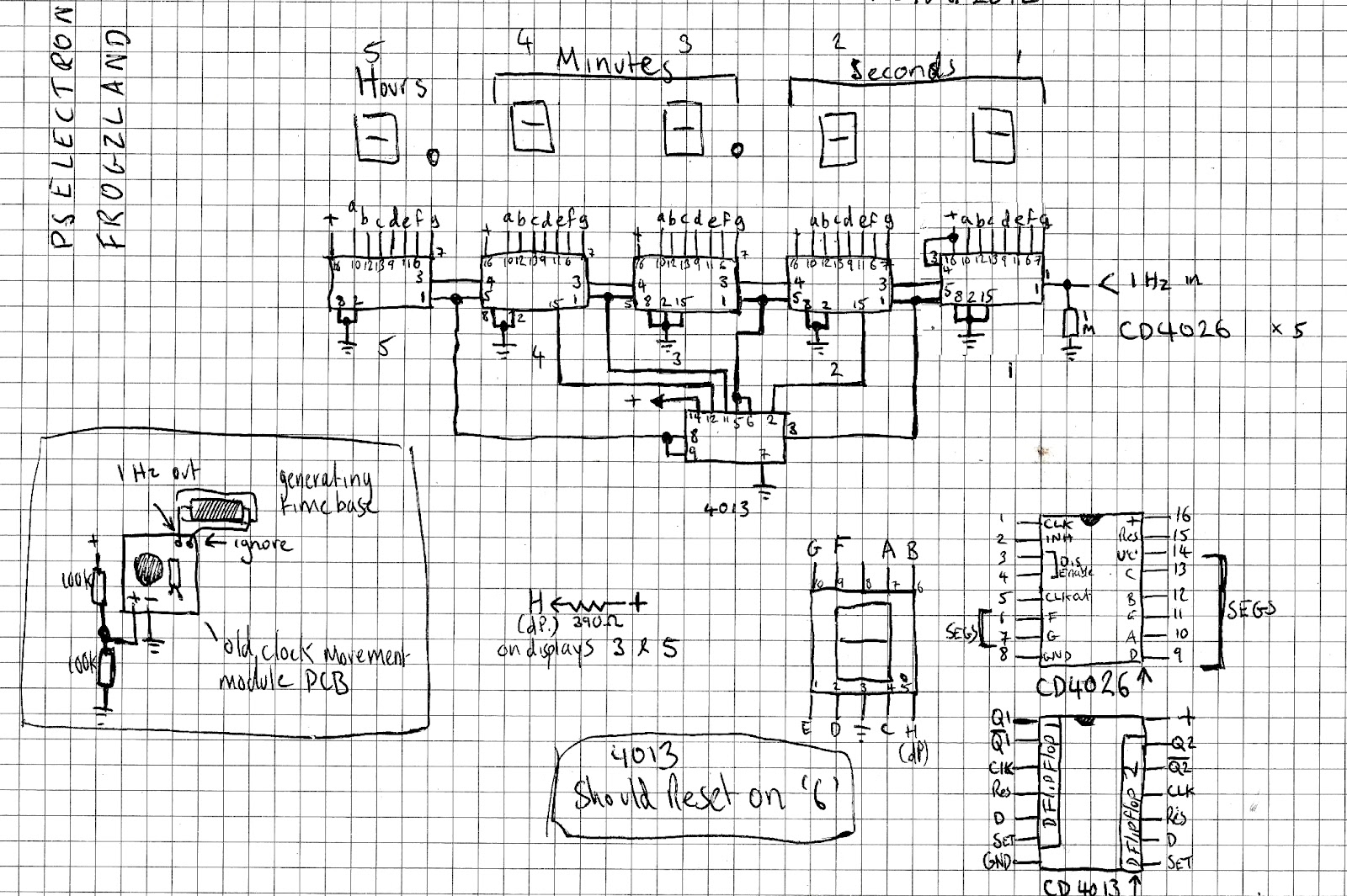
24-Hour Digital Clock and Timer Circuit

Dancing Light using 555 Timer

Simple 1 Hour Timer Circuit with Buzzer - Switched wiring Circuit

24-Hour Digital Clock and Timer Circuit | Best Engineering Projects

Timer of 12 seconds using hardware circuit - Electrical Engineering

Solved: Refer to Fig. 12-21. When the count on the timer reaches 0

delay circuit Page 4 : Meter Counter Circuits :: Next.gr

24 Hour Timer :: circuit diagrams

Two 24-Hour Timer Circuits 2 - Control_Circuit - Circuit Diagram

Master Electronics Repair !: 24 HOUR TIMER CIRCUIT SCHEMATIC DIAGRAM

Paul In The Lab: A Word On My Schematics and a 10 Hour Timer